

STEP BY STEP GUIDE ON HOW TO TRACE AN IMAGE FOR YOUR CNC CUTTING WITH VECTRIC
If you've ever wanted to add some intricate elements of designs to your CNC projects, but don't have the know how to create one from scratch, i2R is here to teach you the easy solution of image bitmapping.
Image bitmapping is the act of taking a digital photo and converting it to a vector outline that can be used to create a toolpath for your CNC. For this walkthrough, we will be using Vectric's V-Carve software.
Step 1: Get a Photo
When selecting a photo to trace, don't forget to keep it simple - at least at first. Using an image that is either monochrome, or in black and white will allow V-Carve an easy boarder definition to trace automatically. For this example, I'm tracing NASA's all red logo, but feel free to follow along with any image you prefer.

I'd recommend finding a high resolution photo, that way there will be less noise and line jitter.
Step 2: Import into V-Carve
When you open V-Carve, set your material size and machining preferences to whatever best suits your image, then press "OK".
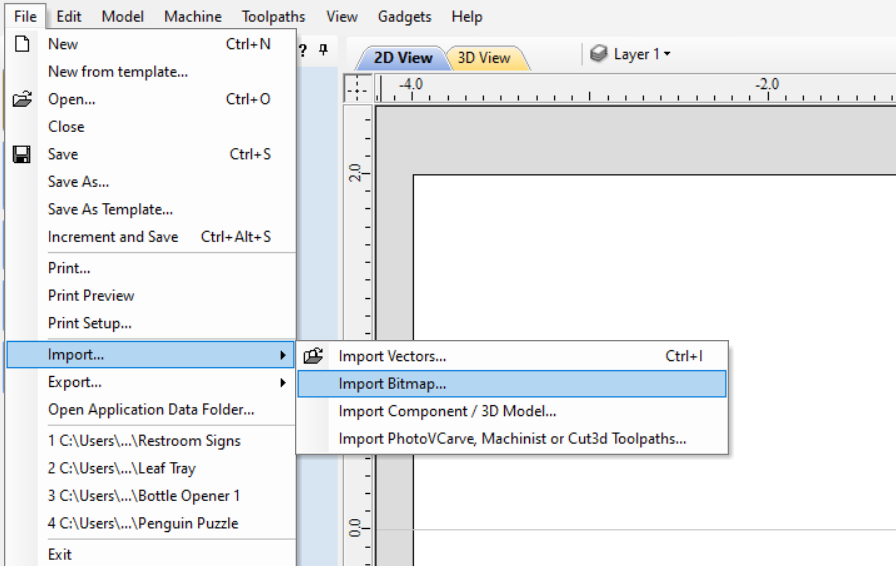
Next, you can import you're photo either by dragging the file over the V-Carve window, or by going to File -> Import...-> Import Bitmap... and selecting your photo.
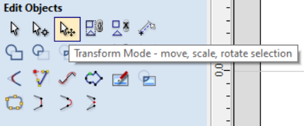
Once it's in the V-Carve program, you can resize it to the desired dimensions by using the Transform Mode tool and dragging the corners.
Step 3: Bitmap Tracing
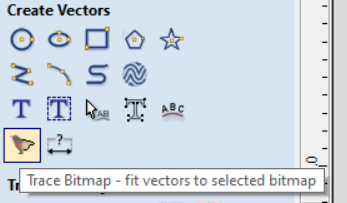
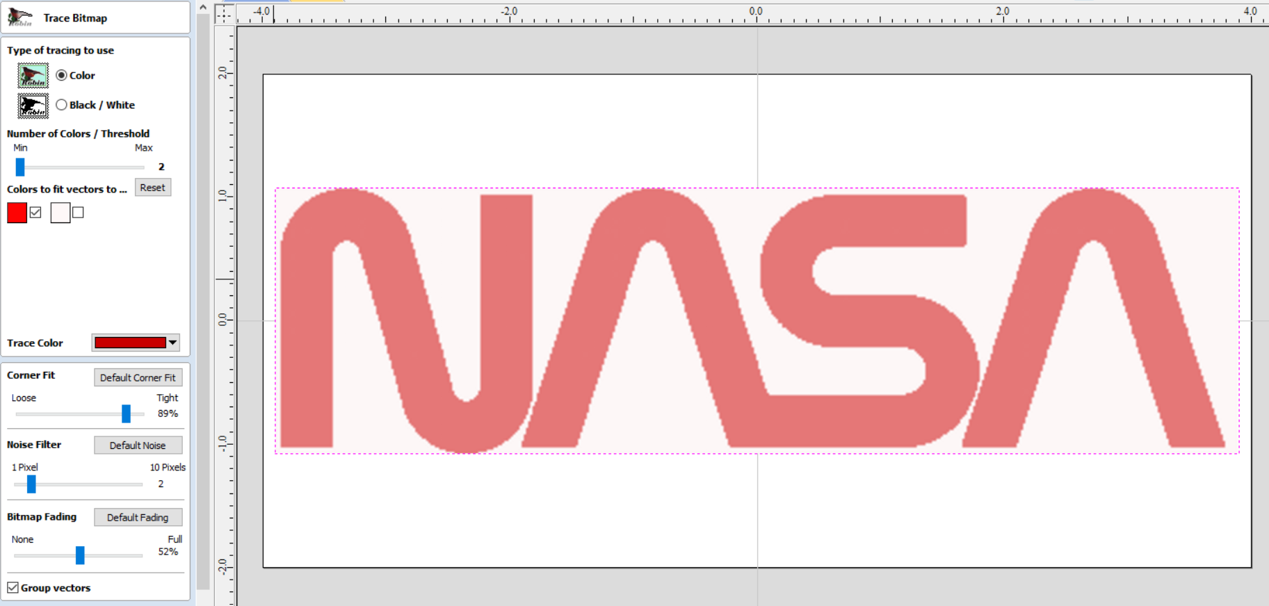
Now that you have your image in place, make sure it's selected and press the "Trace Bitmap" button under Create Vectors. This will open up a new window that allows you to adjust the settings before V-Carve makes the vectors.
Under Type of tracing to use, Select whichever pertains to your image (Color or Black and White). Since we're keeping it simple, there won't be much difference in the process of either choice.
Next, adjust the slide bar under Number of Colors / Threshold.
- For monochrome images: set to the minimum (2 - the color of your image and the background.) Then, under Colors to fit vectors to ..., only check the box of the image color.
- For black and white, it's best to adjust the slide bar to whatever your preference is. The closer to Max, the thicker your lines will be, and vice versa.
After those settings are squared away, you'll want to do some fine tuning with the bottom 3 slide bar settings:
- Corner Fit: This setting will tell V-Carve how close you want it to "hug" the corners defined in the image. The closer to "Loose", the more curved your angles will be. The closer to "Tight", the sharper your angles will be.
- Noise Filter: This setting comes in handy when you are working with a relatively low quality image. The number value indicates the amount of pixels that V-Carve will ignore in a group. You will need this if your preview bitmap has small circles scattered across the image. By adjusting this slider, V-Carve will know when those small groups are mistakes or intentional.
- Bitmap Fading: This setting doesn't effect the actual vector lines created, but instead is a previewing preference for the intensity (opacity) of the original image. Sliding down will fade the image away to "None", sliding up will make the image more visible until "Full".
The nice part about these settings is there's no "right answer" for any of them, it's all up to personal preference and how you want the final image to look.
You can periodically check on what your vector will look like by pressing the "Preview" button as you adjust the settings. Once you have the line how you want it, press "Apply" to create the vector lines.
Step 4: Adjust the Lines
As great as V-Carve's bitmap trace feature is, it's not alway going to give you the perfect outline. That's where good old fashion manual labor comes in.
First, select the created lines and press "N" on your keyboard. A window will pop up prompting you to "ungroup the selected objects." Press "Yes". (This step can be avoided by unselecting "Group vectors" box at the bottom of the Trace Bitmap window.)
This will bring you into Node Editing Mode. Your line will show these black, green, or blue dots, these are the Nodes- think of them as benchmarks for your overall line. You can adjust these lines by clicking and dragging the nodes, deleting them, changing them into curved smooth points, and more. The best way to get comfortable with this feature is to play around with those features. Right clicking on a node will bring up a menu that lets you manipulate the node, and tells you the shortcut key for each action.
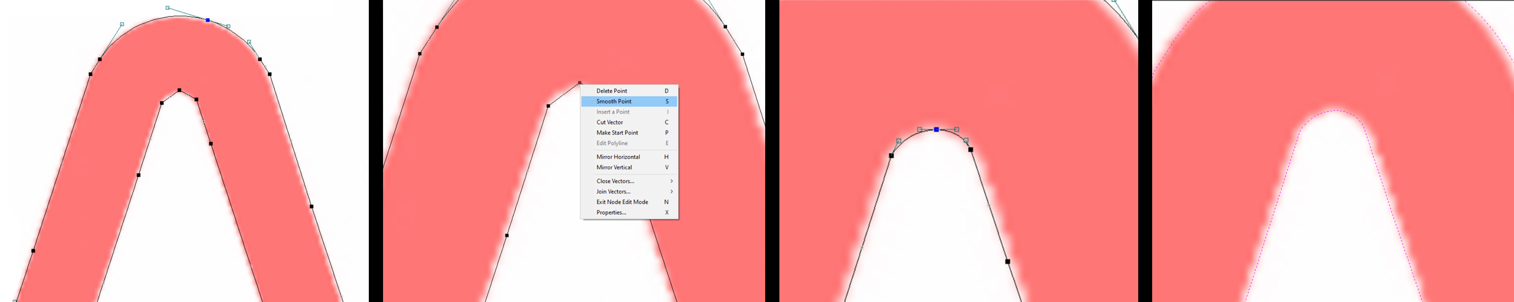
Use these features to fine tune your lines- but don't get bogged down by the small details- some of the really small things wont be noticeable after the cut. The most important thing to do is look at your design as a whole (zoomed out) and see if it shows what it needs to.
_____________________________
From there, you're ready to make your toolpaths. This will be different for each job based on material, dimensions and thickness, size of design, and available bits, but be sure you are using the "Preview Toolpaths" feature and adjusting your lines as necessary.