Node Editing
Node editing can now be performed on multiple vectors selected at the same time. Making it easier to access all the nodes and spans in your job for multiple editing, without having to access each vector individually.
|
 |
We have also added the ability to transform your vectors directly from the span itself allowing you to drag individual spans and change their shape in the case of arcs and Beziers, or moving the whole span in the case of lines for a much easier, intuitive workflow to get you to the shape you want. In cases where you have two open vectors, you can select the end points of each vector and join them together whilst remaining in node edit mode using the right click menu, you can then join them with a straight line, a curve or the mid point between the two.
|
 |
Maintain Object Rotation
When rotating and scaling objects, the original bounds are now maintained. Allowing you to scale rotated objects along their axes more easily and intuitively. When we scale the size of a rotated object we can now scale the part in line with the rotated bounds of a selected object.
|
 |
To accommodate this enhancement, we’ve also updated various transformation tools to include the rotated bounds when making transformations to a rotated vector, For example; In the move tool we can now move objects relative to their rotated bounds.
|
 |
In terms of rotation you can now rotate objects to an absolute value as well as a relative value to the current bounds.
|
 |
When working with rotated objects in the mirror tool we can check the option to use rotated bounds and all mirroring applications will be relative to the bounds of the rotated object.
|
 |
When working with the distort tool on a rotated object we can now edit the envelope within the rotated bounds making it much easier to control the shape of the distortion.
|
 |
Bitmap Improvements
When importing bitmaps you now have the ability to rotate it directly in the software using the rotation handles on the corners of the image.
|
 |
Font List Favourites
The font list in both the ‘create text’ and ‘create text within a vector box’ form will now save the 5 most recently used fonts at the top of the list to allow quicker selection of frequently used fonts, that way you save time searching for your favourite fonts. The number of recently used fonts displayed can easily be edited in the program options form to a number you are happy with.
|
 |
Welding Text
The welding tool includes the welding of text objects all at the click of a button! Which is perfect for overlapping style fonts. Simply select your text, use the weld option where it will keep all of the internal regions of the text characters. You also have the option to keep or replace the original text object.
|
 |
Dynamic Text on a Curve
When text is placed on a curve, its anchor can now be freely moved, rather than being limited to the standard three predefined locations of left right and centre, we can now move the anchor to give us much greater control of the position of the wrapped text. Another enhancement we have made is that the wrapped text can be detached from the original curve and still be re-worked in the wrap text form, where it remembers the original settings of the wrap if you wanted to make further changes.
|
 |
Add Side Length to Polygon Tool
We have added an extra option in the draw polygon form where you are now able to create a polygon by specifying the length of a side. For example if you want to create an equilateral triangle where all the sides are 2 inches long you can simply specify this in the form and the software will create it.
|
 |
Shape Editing Shortcut
We have added a shortcut to quickly get you into a shape form for further editing. If a vector is selected which is able to be modified using one of the shape drawing tools, (circle, ellipse, rectangle, polygon or star) then by simply pressing ‘E’ on the keyboard the software will now automatically open the correct shape creation tool for the selected shape.
|
 |
Space Selection Behaviour
The space selection controls in the alignment tools form will now maintain the X or Y ordering of any selected vectors and space them between the top and bottom or left and right items in the selection, regardless of what order we selected the vectors in.
|
 |
Nesting & Double-sided Nesting
When nesting parts it is easy to see what parts will be nested before applying the nest command. When you select your vectors for nesting, the software will indicate what it believes to be “parts” and you will see that represented by the thick black outline, any vectors that overlap an outer boundary will be included in the outline for the “part” and any vectors that lie inside the bounds of the outer vector will be highlighted with a brown colour (if the “allow parts inside other parts” option is checked) and this is to represent areas that the software identifies as “holes” in the work piece. With the addition of displaying the outer boundaries for parts to be nested these outlines will be used during the nesting process and so parts will be nested in a much more space efficient way.
|
 |
TWhen working in a double-sided job the nesting form will automatically switch on the nest two sided parts option, allowing you to nest vectors on both sides of your material. Again the visual indicators are handy so that you are able to visualise whole parts where vectors overlap each other on both sides.
|
 |
Design & Make Bundle Selection
When upgrading or purchasing version 10 you are entitled to select one free model project worth $55 courtesy of our sister company Design & Make that you can use in the software. At the point of purchase you have a one time opportunity to purchase any of the full collections at a discounted price. Where there are four themed model collections to choose from that have been professionally created and are ready to use on your CNC.
|
 |
New Clipart
We have added over 40 new pieces of 2D clipart to help you get started with all sorts of projects. You will find game layouts and moulding profiles for use with the moulding toolpath. We have also included vector rotary profiles that you can use to model spindles in a rotary job. There is a selection of stylized words which would be perfect for VCarving and we have also included 40 texture fill tiles that have been carefully created from the existing tile clipart using the texture area tool, so all you need to do is drag the tile out and it will fill out with the pattern it was created from.
|
 |
Copy Dragging of Components
Easily copy components into other levels of your job by simply holding down the ‘Ctrl’ key on your keyboard whilst dragging the component into a different level ensuring that your assembled part.
|
 |
Replace Below
We have added a new model editing tool which replaces the “replace below” gadget. This tool allows you to trim or flatten the bottom of a component(s). For example if you’ve imported an STL model that has a lot of thickness, which can be quite typical of 3D scanned data, this tool will allow us to simply trim away the unwanted thickness. Another scenario could be that you have created a negative area in your model for example when sculpting or combining a component with a deep subtracted model, this tool will easily remove anything below a given height. This height can be manually typed in or you can simply double click on an area of the model itself that we want to remove and the form will update according to the Z value of where you have clicked. Simply select if you would like to replace this with transparency or a plane. The final option also allows you to drop the component by the value we are removing to, to help keep your models to standard relief heights.
|


|
Sculpting Enhancements
If you have a favourable setting for a particular sculpting tool and application you can save the settings as a pre-set that you can name and access in later sessions from a drop down list to quickly reinstate those settings.
|
 |
We have also added the option to overlay a bitmap image over the component you are sculpting, this is perfect for when you are sculpting areas that require you to refer to the original image you are working from to help you get the model to a finished state, for example faces and animals. To help achieve this you have the ability to alter the image opacity, to reveal as much or as little of the bitmap as you would like.
|
 |
Level Clipping
The level clipping mode makes it easy to constrain the model you are creating to a chosen boundary. Use vectors to define your boundary and the contents of your level are dynamically clipped so that only what lies inside the vectors is kept. This makes it simpler to assemble different models and allows you to rearrange your components and see the results of clipping in place.
|
 |
Photo VCarving Toolpath Strategy
Use the PhotoVCarving toolpath strategy to convert photographs and images into toolpaths producing stylised engraved designs. The created toolpaths engrave a series of lines at different depths to produce the desired image.
|
 |
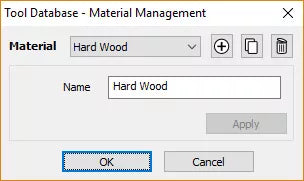
Tool Database
The tool database has been given a significant overhaul. You can now add parameters relevant to different machines or materials. For example if you use the same tool, but want different speeds and feeds for different materials, you can now adjust the parameters based on the material you’re using. Once your materials are set up and you are ready to machine, you can filter the tools so that you only see the ones that are compatible with the material you’re using. Use the new tool naming mechanism to consistently name your tools. Ensuring that the tool name always matches the tool dimensions. It even supports displaying inch tools correctly. You can now view the chip load on the tool from within the software.
|


|
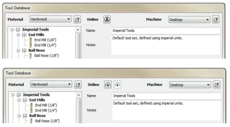
Online Tool Database
It is now easy to share your tool database across the machines you use. The new tool database can be synced with your online V&Co Account so that changes made to the tool database on one machine are reflected across your other running instances.
|
 |
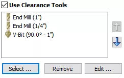
Optimizing Clearance Tools in VCarve Toolpaths
The VCarve toolpath now supports multiple clearance tools for more efficient area clearance. This can help shorten machining time and reduce tool wear. Using multiple tools means you can use a much larger area clearance tool, and intermediate V-Bit tools to ensure that the fine detail tool only needs to remove the smallest amount of material possible.
|
 |
Lithophane Preview
The lithophane preview mode provides a simple way to visualize the lithophane effect on your simulated toolpaths. Just enable the mode from within the simulation and use the slider to adjust the brightness to suit.
|
 |
Depth First Roughing
The roughing toolpath strategy has been enhanced to add an additional ordering type. The ‘depth first’ option can now be chosen. This strategy machines regions to the desired depth and then moves onto the next region rather than machining all the regions to a fixed level. For models with distinct separate regions this can be much quicker and result in significantly fewer air moves.
|
 |
Toolpath Groups
Toolpaths can now be grouped within the toolpath tree. Organize your toolpaths into logical groups to make managing complex jobs more straightforward.
|
 |
Apply Templates to All Sheets
Loading a template will now ask if you want to apply that template to every sheet in the job. Any toolpaths generated will be prefixed by their sheet number and grouped in the toolpath tree.
|
 |
Toolpath Merging
Toolpath merging is a powerful tool for combining separate toolpaths into a single more efficient toolpath. It has been enhanced by allowing you to edit and modify all the original toolpaths whilst still maintaining the merging information. The operation now produces a parent toolpath and contains all original toolpaths as a sub toolpath. Each sub toolpath can be modified, and the merging is automatically updated.
|
 |
Rotary Toolpath Projection
Toolpaths in rotary jobs can now be projected even if they fall outside of the job. This allows for easier creation of spiral toolpaths.
|
 |
Material Importing
New material textures can be easily added to the software. If you have a picture of the material you want to add you can just select ‘add new texture’ from within the appearance drop down menu to use that image for the material texture.
|
 |
Tab Resizing
The toolpath tab is now resizable. Expand it to fit even the longest of toolpath names.
|
 |
Default File Dialogs
You can now use different settings for default file locations. Choose to have the software remember specific locations for specific actions, e.g. always open images from my `pictures` directory. Or you could choose to always open the file dialogs in the folder of the current project.
|
 |
VCarving Text & Intersection Detection
Text is welded automatically with the Welding Tool before being V-Carved without it actually affecting the text object. Making the process quicker, this also avoids issues arising when characters intersect with each other. Another improvement that we have added to the VCarve Toolpath is the ability to detect and warn users about the presence of intersections within the selected vectors, where the software will prompt you on calculating the toolpath to run the Vector Validator to help locate problematic areas. Within the Vector Validator the software will automatically put you into VCarve mode where the software will ignore the intersections that would be welded by the toolpath itself. And focus on areas outside of the VCarving mode, helping you locate the issues before the toolpaths are simulated.
|
 |
Post Processor List Favourites
When you save out toolpaths we have made it easier to locate your favourite posts where the post processor list will now save the 5 most recently used post processors at the top of the list allowing for quicker selection of frequently used posts!
|
 |
Integrated Help
Help for all forms can now be found using the integrated help function, which can be found if you click on the question mark icon on the top of each form to get the help for that specific function.
|
 |